


Homag CNC Router Cell (Used)
CENTATEQ N-300/510 V12 manufactured 2016 installed 2017; 460v; 3ph; 60hz.
This machine was installed and never used. It was only run by the installation techs.
Company has changed hands and the machine was never used in production.
Weeke Vantech 510 V12 PRO+
CNC Machining Center with
Concept 2 Throughfeed Automation
Basic Machine
Solid machine foundation provides the rigidity required for high speed
gantry movements and machining operations.
Gantry movable in X direction
Cross support movable in Y and Z direction
Gantry enclosure
Safety fence at the machine rear, right and left hand side
Light barriers for safety at the machine front
Machine is pre-wired to accept remote operating pendant
Machine frame is pre-configured to accept a gantry mounted push off
device and additional material handling elements
Guide System and Drive Technique
High quality THK style linear guiding system
Toothed rack assembly (synchronous drive) in the X-direction and ball
bearing screw for movement in Y and Z direction
Digital drive technique in X, Y and Z direction featuring:
o Maintenance free motors with high resolution optical encoders ensuring
precision accuracy
o Digital drive control units guarantee high reliability
MATRIX Table 5′ x 10′
A grooved phenolic MATRIX vacuum system for holding down work pieces comes
standard. The grooves provide for efficient distribution of vacuum, as well as
isolating table areas by inlaying a rubber sealing and/or accepting vacuum pods for
fixturing small parts.
The MATRIX system offers:
Vacuum system for clamping of the work pieces on the surface of the
vacuum table
Can be equipped with optional Pod System for elevating parts
Working table length: 3100 mm (10' / 122 Inches)
Working table width: 1550 mm (5' / 61 Inches)
Workpiece thickness: maximum 100 mm (3.94 Inches)
o Includes rubber gasket material
PRO+ Matrix Table – 8 Vacuum Fields
By dividing the matrix table into 4 zones, reading the raw material size of the
incoming program and automatically concentrating vacuum pressure to the correct
area of the machine, the PRO+ solution is perfectly suited to handle the raw
material variance of today’s multi-faceted manufacturers. The machine is able to
automatically create 4 optimized vacuum zones: 4’x8’, 4’x10’, 5’x8’ and 5’x10’.
The vacuum fields that create zones A1 and A2 can also be semi-automatically
selected at the machine control.
Note: fixture board material (also referred to as “bleeder board” or “spoil board”) is not
supplied with the machine, but required at time of installation.
Vacuum System
The machine design includes (4) four vacuum pumps with a total vacuum
capacity of 356 m3/h, 60 Hz. They are directly connected with the vacuum
table via a distribution device and one of the three vacuum generators
serves as master.
The vacuum system is one of the largest electrical consumers of any
manufacturer’s machine. For this reason, the Vantech system utilizes an
Eco-Friendly design to conserve energy and on electrical costs. The pumps
operate from a “staggered start” to reduce the maximum draw of the
machine upon start up and single pumps can be switched off to save energy
when not required.
Vacuum pumps are activated via soft key at the control panel,
outperforming common manual vacuum valve systems.
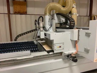
Vertical Router Spindle – Rated at 16.1 HP
HSK63 spindle motor that includes an automatic tool change feature in
combination with the tool change magazine.
Direction of rotation: right hand / left hand
Speed: 1,250 - 24,000 rpm stepless programmable
Drive: frequency controlled to a maximum capacity at the tool: up to 7.5/9
kW (10/12 HP) in continuous and intermittent operation (S1/S6 - 50%)
Spindle lubrication: permanent grease lubrication
Bearing: hybrid bearing (ceramic), little friction, higher stiffness and
maximum operating life
Fan cooled
Central dust extraction
Multi-Zone Processing
The table and control interface on the Vantech machine is configured to
allow the operator to simultaneously load multiple programs at up to four (4)
zero points of the machine (number of zero points determined during
machine specification). The machine can then optimize drilling and routing
routines and run the multiple programs as a single file.
This is an important feature for those who may use the Vantech machine as a
“point to point” machining center or provide back-up to that style machine
already in operation on their shop floor. Customers who run 5’ x 5’ raw
materials (Birch Plywood for example) also like the feature because they can
run two sheets of raw material side by side in a single machine cycle.
Air Jet Agitation
Four flexible air jets are integrated into the extraction hood providing a cool, clean
and efficient machining area. Air jets are activated via soft key at the control panel.
Automatic Tool Change
To increase flexibility and decrease cycle time, an automatic, rotary tool changer is
arranged near the rear right of the machine framework.
Features:
Tool holder: HSK63
Magazine places: 13 tool places
Tool weight: maximum 6 kg (13.22 lbs) including HSK cone
Tool diameter: 130 mm max when equipped with tools
Tool change time: approximately 10 - 18 seconds
Automatic Tool Loading Position
The Vantech provides a single point of interaction for loading and unloading the
tool changer. Operator efficiency is increased by allowing the machine to take
some of the responsibility for managing tooling. Tools are manually inserted into
the loading device, positioned close to the left front of the machine for easy access.
The machine retrieves the tool and selects the first available position in the tool
magazine, deposits the tool, and updates the tool database.
The system has proven an effective method for minimizing tool and machine
damage caused by errant manual loading of tools into the machine and/or incorrect
entering of data into the machine control. The process is reversed for removing
tools from the machine; the machine deposits tools in the loading position and
automatically removes the tool from the active tool database. The loading position
also utilizes a sensor to prevent the machine from depositing a tool in the position
while another tool is present.
Tool Length Control
A heavy duty tool length control system is a standard feature of the machine. To
maintain accuracy, tooling is touched off after a change via the tool pick-up station
and its length is verified against the tool data stored within the machine control.
12-Spindle Vertical Drill Block
A vertical drilling block with twelve (12) spindles is included.
Special feature: Spindle clamping to achieve the drilling depth safely.
Stroke Z-direction: 60 mm
Drilling depth: maximum 35 mm
Direction of rotation: right hand/left hand
Speed: 3,450 rpm
Power: 1.5 kW
Shaft diameter: d = 10 mm
Total length of drill: 70 mm
Drilling diameter: maximum 35 mm
Distance between spindles: 32 mm
Type of spindle: individually selectable
Spindle Arrangement: X-9 spindles, Y-3 spindles
Pneumatic Side Reference Fences and Locating Pins
Supplementing the pneumatic reference pins delivered within our standard machine
configuration, full length solid fences serve as the means for locating materials to
the working zones of the machine. Paired with a pneumatic reference pin located at
the front right and front left of the machine, the system offers two “zero” points for
accurately locating raw materials. Fences retract during machining. When the
finished nest is ejected, the fences are raised again to help guide parts from the
machine table to the transfer conveyor at the end of the machine. Both the fences
and the pins are under down stroke surveillance to prevent the machine from
routing a fence or pin in the event of an incomplete cycle
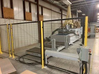
Automatic Loading Device for Raw Boards
Porous Materials Loading Features
Consistent with Weeke’s reputation in the marketplace, the attention to detail
in the CONCEPT 2 loading system design from Weeke is second to none. In
addition to the industrial load/locate features of the Weeke system, we have
also paid a great deal attention to the machines ability to load and locate
porous materials. This is a challenge not considered by many customers until
machines have been delivered. The Weeke system utilizes two 10” diameter
Schmaltz vacuum cups integrated with both vacuum and compressed air.
Blowing the proper amount compressed air through porous raw materials
during the loading cycle allows the machine to retrieve the raw material
without picking up more than one sheet. The vacuum grippers can also be
setup to peel the raw sheet from the bunk and also shake the sheet prior to
loading to ensure not more than one sheet is being loaded to the machine
table (from vacuum bleed thorough or static between sheets).
The machine is equipped with a gantry mounted vacuum loading apparatus for
automatically loading non-permeable materials to the machine from a stack of
material positioned on a scissor lift at the left of the machine. Working in
conjunction with an intermediary section of roller conveyor, the side fences noted
above, and a sensor in the guide area, the machine is able to automatically load
itself, and accurately position the raw sheet for the start of the machining cycle.
Scissor Lift for Positioning Material for Automatic Loading
Weeke’s Concept #2 handling package utilizes a scissor lift to accurately
position materials for automatic loading with the gantry mounted vacuum
device. The lift features a 5,000 lb load capacity noting the ability to accept
roughly 32 sheets of 5’ x 12’ 3/4" particle board melamine material, based
on an estimated density of 46 lbs/ft³, the capacity of the lift and the elevation
of the machine table.
The lift platform is designed with 2 ½” diameter rollers set high on 4”
centers, 11 gauge, 58 ¼” overall width. (2) 30” long section mounted at each
end of the platform to allow (2) 14” spaces for fork lift access. (2) floor
mounted alignment columns – 1/2” base plate, 4” square tube upright and
3/8" face plate, 12” wide are included to provide means to align the bunk in
the long (X) direction. A full height, heavy phenolic plate is affixed to the
machine base to allow for accurate positioning in the short (Y) axis or width
direction. Once the material is loaded on the lift and aligned in (X) or length
axis by the fork lift, the operator guides the material by use of the roller
conveyor on the platform to the location of the phenolic plate to accurately
position the bunk in the (X) axis direction. Once the bunk is in position, the
operator accutates a pneumatic friction brake to lock the bunk in place.
Lift Platform Automatic Leveling Package: This feature automatically
brings the bunk of material to the proper elevation for loading. The lift is
wired to communicate with an adjustable photoelectric sensor and control
panel mounted to a stanchion. Panel includes Index On/Off selector switch,
lift Up/Down selector switch, and an E-Stop button. An adjustable timer is
included to delay (up to 10 seconds) the automatic movement of the
platform. A separate stanchion with reflector is also included for upper limit
switch for indexing up
The lift notes a lowered height of 12 3/8” to top of roller and a raised height
of 60 3/8”, noting a vertical travel range of 48”. The power unit is 1.0 HP
TENV electric motor and .85 GPM hydraulic pump, no-coast valving for fast
movement and decreased upward coast producing more precise positioning.
All pivot points are equipped with Teflon lined bushings, leg rollers feature
wear indicators.
Intermediary Roller Conveyor
Once material is retrieved from the scissor lift by the machine, it is carried
across a section of roller conveyor complete with protection to prevent
scratching of the raw materials.
Automated Push-Off of Finished Nests
To complete the “throughfeed” concept of the machine, the system utilizes a
gantry mounted push-off device to automatically eject finished parts from the
machine table without manual operator intervention. Once the nest is
complete, the machine returns to the loading side of the machine, drops its
push-off device and cycles from left to right, collecting finished parts and
waste along the way. The unit also contains a table cleaning sweep
integrated into the push-off to clean dust and debris from the spoilboard in
preparation for the next raw board.
Simultaneous Onload and Offload
To further increase the efficiency of the system, the machine is able to utilize
a simultaneous onload and offload feature, effectively unloading the finished
nest, cleaning the spoilboard, and loading the next raw sheet in a single
cycle.
Dust Extraction from Below
A bottom dust collection channel with blast gate is integrated into the machine
frame to collect dust from the nest as the parts are ejected from the machine. As
the vacuum from the table competes with the dust collection for the waste, some
dust will remain in the cut. The dust collection channel from below collects this
dust as the parts are pushed from the machine and onto the transfer conveyor. This
feature ultimately leaves less mess to manually clean at the end of a shift.
Transfer Conveyor
A conveyor belt receives the finished parts and automatically advances them to the
operator for sorting at the end of the table via communication with photo-electric
sensors. This allows the machine to process parts while the operator is unloading
the previous nest and prevents parts from being pushed off onto the floor if the
operator is not present to receive them. Minimum recommended part thickness for
consistent part conveyance is 12mm (1/2”).
Dust Collection from Above
The transfer table is also integrated with a dust collection hood from above to clean
residual dust from the top of the work pieces and the conveyor belt. This small
feature proves very valuable for those applying barcode labels or other methods of
identifying parts coming from the router, as the parts are free from much of the dust
and debris of the machining process.
Vantech Maintenance Kit
A tool kit is included with the machine consisting of: 46mm single open end
wrench, 58x62mm hook spanner wrench; grease gun with hose, grease and ball end
allen wrench set.
Power Control PC85T
The Vantech 510 CON2 features a Microsoft Windows 7 based control complete
with intuitive software. The included woodWOP 7 programming system is the
heart of the machine and is unmatched by any programming software available with
a machine today. The powerful drawing functions offered by woodWOP 7 simplify
programming for operators without CNC experience and provide the premium
features required to satisfy advanced users. In addition to the software within the
machine control, a copy of the program is included for installation on an office PC
for off-line programming.
Hardware:
17” flat screen monitor, keyboard and an industrial PC
Operating system Windows 7 (US)
PLC control according to international standard IEC 61131
USB connection at the operating panel
EtherNet connection 10/100 MBIT RJ45 (without switch)
Machine Software Bundle: (software pre-loaded on the machine PC)
PC85T software package with graphical operating programs:
woodWOP 7 for powerful, yet simple generation of CNC-programs
o Graphical tool selection from your database
o Production list administration
o Graphical presentation of work zones
o Clear text error messaging
3D NC-Simulation and Time Calculation: One (1) license
PC85T CNC-Core Includes:
Path control in all axis and parallel sequences by multi-channel technology
Look-ahead-function for optimal speed at the transitions
Hand Control Pendant
Remote terminal with potentiometer, manual control of machine axes and
emergency stop switch.
Software for External PC - Single Seat Licenses for the Following Programs:
Requires computer operating Windows 7 or 8
woodWOP 7 for powerful, yet simple generation of CNC-programs
DXF-postprocessor Basic for the data exchange from 2D-CAD-programs to
woodWOP
o Import of 2D-DXF-files via pre-determined layering rules
o Display of geometry, layer and drawing elements
o Generation of woodWOP program files
Schuler MDE Basic for machine data recording
WoodNest Basic
o Software for the Nesting of woodWOP program files
o Manual positioning and turning of work pieces by drag and drop
o Visualization of spacing between work pieces
woodWOP MOSAIC
o Software to view thumbnails of woodWOP files
o Allows woodWOP data files and complete directories to be
managed from a graphical point of view
o Programs can be administered by drag and drop
WoodType
o Software to generate routing contours for characters and texts in all
available Windows True Type fonts
Manuals and Control Texts
Standard Manuals, CD, as well as .PDF versions stored on the machine
containing operating and maintenance instructions
Display texts for machine operators of the POWER CONTROL
Spare parts descriptions consisting of CAD-drawings and wiring diagrams
Technical Specifications
Utility Requirements
Electrical
Operating Voltage 480 Volts / 3 Phase / 60 Hz
Amperage Service 50 Amps @ 480 Volts
Control Voltage 24 Volt
Total Connected Load 27.5 kW
Dust Extraction
Connection Sizes (2) 200 mm, (1) 160 mm, (2) 140 mm
Air Velocity (minimum) 28 m/sec - 92 ft/sec
Static Pressure Minimum 2200 Pascal
Air Volume 8300 m3/h – 4885 cfm
Compressed Air
Connection Size(s) R ½ inch
Pressure Required 100 psi – 7 bar